Get a free quote
Fill in the form below and give us a rough idea of your application. We will be happy to provide you with a non-binding quotation.


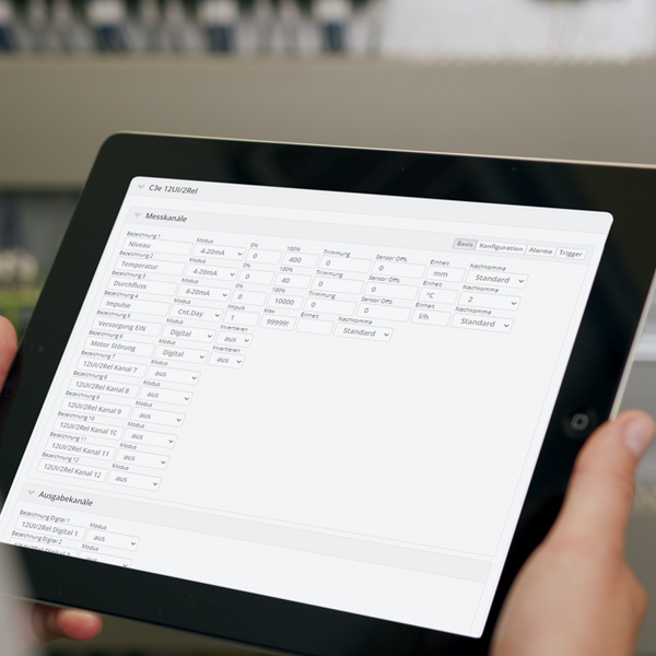


The channels and alarm thresholds are easily configured via the graphical interface on the platform. In addition, you benefit from evaluation and reporting functions. To customize the application to your specific requirements, programming with extensive libraries is possible in the studio.
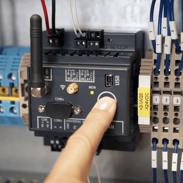
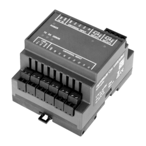
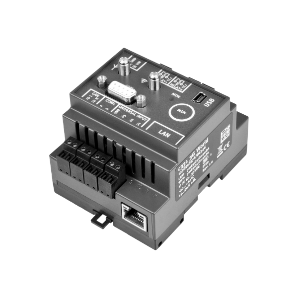
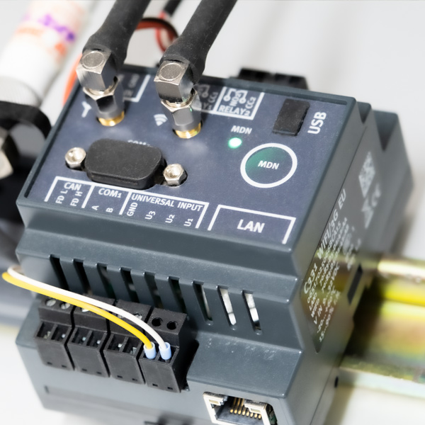
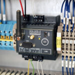
The interfaces are remotely configurable (universal input (4-20mA), RS232, RS485, CAN). This ensures the greatest flexibility. The device is perfectly applicable in automation, control and remote action. The two relays are individually configurable. Sensors are integrated in a few minutes.
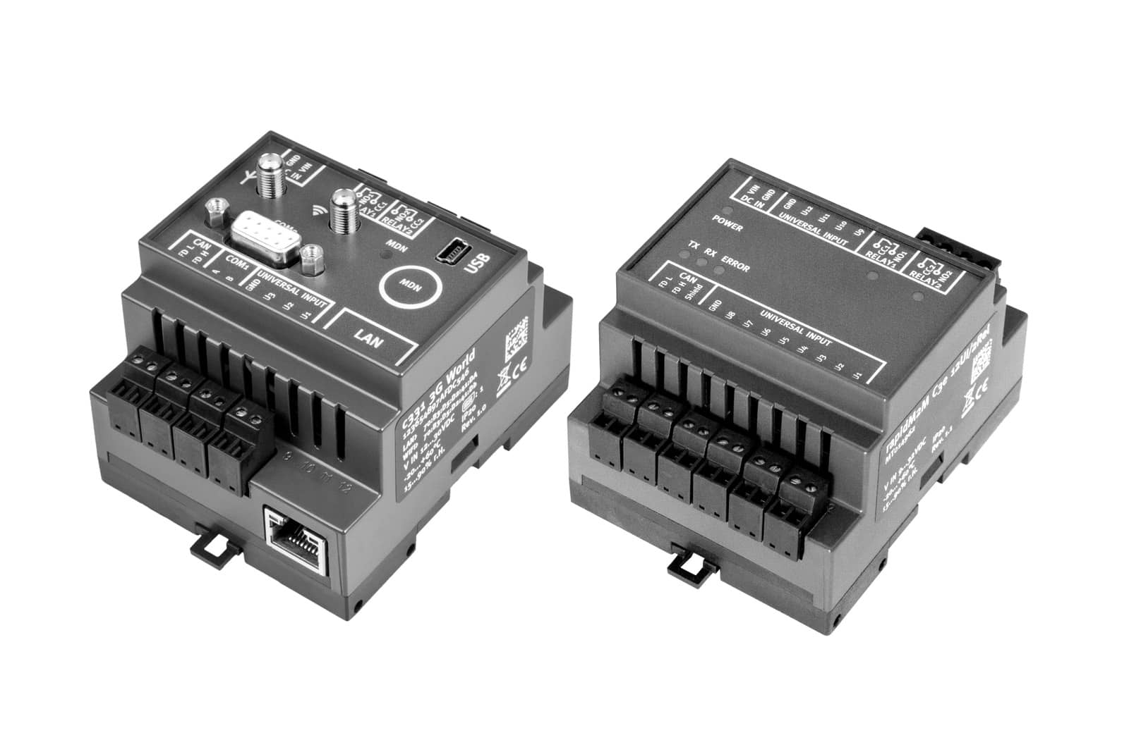
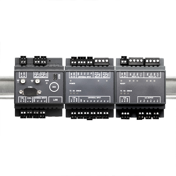
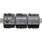
With the input extension myDatalogC3e 12UI/2Rel the base unit gets additional twelve universal inputs as well as two potential-free switch contacts for controlling actuators. The output extension myDatalogC3e 3mA/6Rel expands by three analog outputs and six relays.
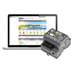
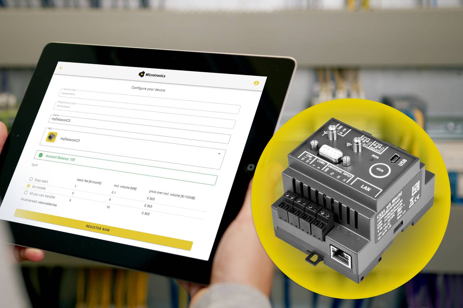
Remotely configure, control and evaluate
With the pre-installed software, the basic functionalities are parameterized user-friendly and graphically on the platform.
Basic functions of the software for myDatalogC3 (optional with extension modules):

Central management
The platform allows you to create alerts, dashboards and reports within minutes. Updates to firmware, applications and configurations are conveniently carried out remotely via the web login – without having to travel to the unit.
Integration into further systems is easily possible via the web interfaces (RESTful API or OPC-UA). This allows, for example, a direct coupling into process control systems.
Modbus RTU/ASCII
The Modbus master library currently supports the master mode for serial interfaces (RS232 and RS485) and is characterised by its universal applicability. In addition, great importance was attached to easy integration into own projects during the development. Zudem steht der vollständige Sourcecode im Studio zur Verfügung. The data transmission can be carried out either in the efficient Modbus-RTU or alternatively in the Modbus-ASCII format. You can find out more here.
Upcoming: Standard software for Modbus configuration. Ask your Partner Manager for more details.