The UI Trigger functionality provides the possibility to evaluate analog signals acquired via the UI channels with high sampling frequency (up to 1kHz) and to compress them according to the configuration.
The processing is done completely on the co-processors of the myDatalogC330 . Thus, the processing performance (H7 CPU with 400MHz, Double Precision Floating Point Unit) can be used and the load for the module (DLO) is low. Trigger event must be processed.
Configuration
| Parameter | Description | Comment |
|---|---|---|
| Samplerate | Sampling or processing grid | [Hz] 1 – 1000 |
| Warmup Time | Time period after initialization before trigger monitoring starts | [ms], u16 |
| Flags | Configuration flags | Activation of the different triggers (MIN/MAX/CHG/ CHGSUM, etc.) |
| Modus Start | Modus Trigger START Start trigger monitoring |
Modi: always on Value > Threshold Start |
| Modus Stop | Modus Trigger STOP End trigger monitoring |
Modi: never Time > Active Timeout |
| Scale | Scaling factor for conversion to the technological unit (e.g. mA → bar) | Float32 |
| Offset | Offset value for technological scaling | Float32 |
| Threshold Start | Threshold for trigger start (Modus Start) |
Float32 |
| Active Timeout | Timeout for Trigger Stop (Modus time > Active Timeout) |
[ms], u32 |
| Delta Scale | Threshold for trigger detection | Float32 Transient detection possible in combination with Delta Time 0 = disabled |
| Delta Time | Time window for trigger detection | [ms], u16 Transient detection in combination with Delta Scale (measured value change must occur within the configured time) 0 = deactivated, i.e. no transient detection,Delta Scalewill be evaluated without time component. |
| Delta Scale Sum | Threshold value for trigger detection (accumulated measured value changes) | Float32 For detection of measured value changes < Delta Scale (over time) |
Triggerevents
START
Trigger sequence is started, check for activated triggers (CHG/MIN/MAX/etc.).
STOP
Trigger sequence finished – check for new START trigger.
CHG/CHGSUM
Delta Scale (in combination with Delta Time) or Delta Scale Sum (summed measured value changes since the last event) was exceeded.
Trigger event CHG and/or CHGSUM must be activated in the configuration flags.
MIN
Minimum value was detected.
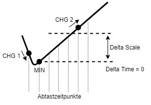
CHG 1 trigger (change > Delta Scale) with falling signal course, CHG 2 trigger (change to minimum value > Delta Scale) with rising. Before CHG 2 is triggered, a MIN event is triggered with the stored occurrence time.
Trigger event MIN must be activated in the configuration flags.
MAX
Maximum value was detected.
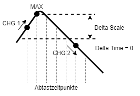
CHG 1 trigger (change > Delta Scale) with increasing signal course, CHG 2 trigger (change to maximum value > Delta Scale) with decreasing. Before CHG 2 is triggered, a MAX event is triggered with the stored occurrence time.
Trigger event MAX must be activated in the configuration flags.
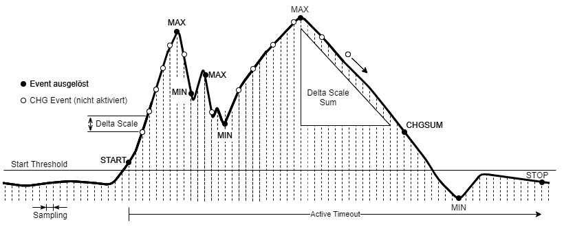
Example
-
- Delta Scale is selected small (in relation to the total signal deviation), but larger than measured value fluctuations, which are to be ignored. Delta Time is deactivated (0), the signal rise time is not evaluated here.
-
- Trigger event CHG is NOT activated to prevent an unnecessarily high number of triggers with little significance.
-
- MIN and MAX triggers are activated.
-
- Trigger recording is started when parameter Start Threshold is exceeded → Trigger Event START.
-
- Optionally, the CHGSUM trigger can be activated, which evaluates the summed measured value changes against the Delta Scale Sum parameter. With the appropriate configuration (form signal/time area), this can be used to trigger a trigger event in the last third of the signal, for example. In this range, the signal drops continuously from the last MAX value.
-
- Trigger recording is stopped after timeout (Active Timeout) → Trigger event STOP.
Timeout because the signal curve itself may not provide a suitable criterion – the signal may become negative and then “settle” to a value around 0 → an evaluation “threshold undershot” would not be accurate here.
- Trigger recording is stopped after timeout (Active Timeout) → Trigger event STOP.