The demo “C3xx 1UI/1Rel Demo” is a simple example of the myDatalogC3. It collects data via a sensor connected to the universal channel. A relay can be switched via the server interface. The demo IoT app includes a simple user interface for configuring and displaying the data on the smartphone.
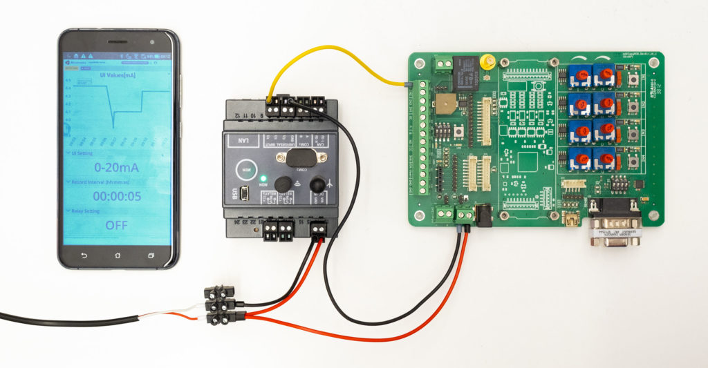
Simple test setup
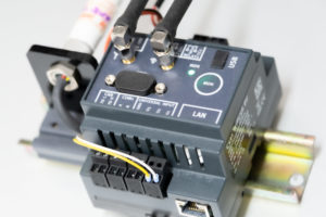
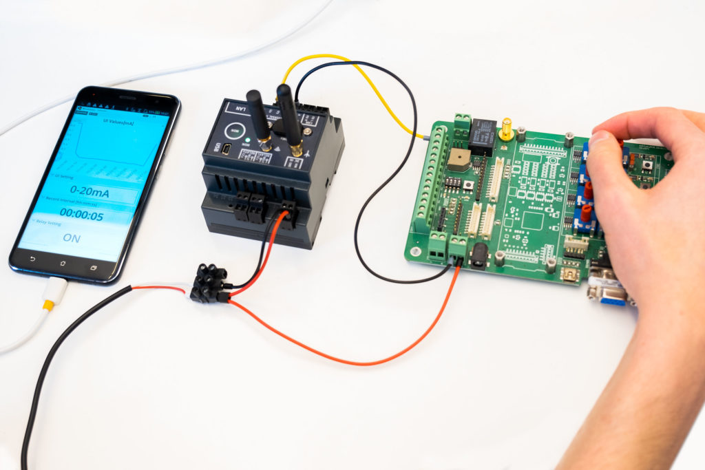
We use a myDatalogC3 in the test setup.
With the help of a development kit we simulate a mA sensor. This allows us to change the mA sensor values in an uncomplicated way. This allows us to quickly see the changes in the measured values in the display.
Alternatively, for the test setup, you can connect a compatible mA sensor to the universal input that you have at hand. A sensor with digital output or voltage output (0-2V or 0-10V) can also be used. The specification of the universal input and connection examples for the different sensor types can be found in the user manual.
Installation of the demo IoT app
To commission the myDatalogC3 and play the demo IoT app “C3xx 1UI/1Rel Demo” into the device use the registration web app at start.microtronics.com .
The registration app not only plays the demo IoT app in our rapidM2M C3, but also creates a corresponding site on the cloud server. Here, the recorded data is stored and evaluated and you can also make configurations.
Web interface
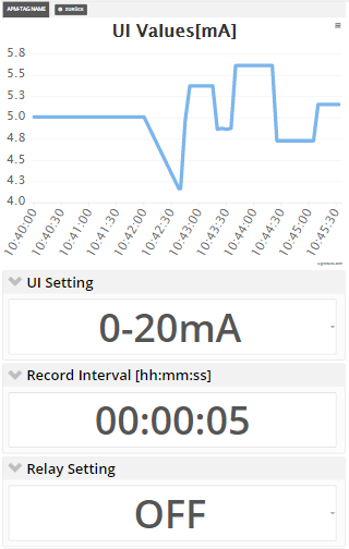
The web interface has been optimised for mobile devices. You can see the recorded data and adjust the settings “UI Setting” (type of sensor connected to UI 1), “Record Interval” and “Relay Setting” (“OFF” = RELAY1 open, “ON” = RELAY1 closed). The changes are applied without explicit saving.
Deep-Dive: Technically speaking, this custom view was created with the so-called Portal View (POV). The Portal View is part of the demo IoT app and is based on common web technologies (Vue.js framework; pug/less with css and JavaScript).
Getting Details: What does the demo IoT app do exactly?
The demo IoT app consists of a Device Logic (DLO), the logic on the device, and the Portal View (POV), a custom server interface.
To make changes immediately visible, the “C3xx 1UI/1Rel Demo” uses the so-called online mode. This means that as soon as the rapidM2M C3xx is supplied with power, it establishes and maintains a connection to the server. On the one hand, this means that the recorded data records are immediately transmitted to the server and can be displayed immediately via the user-defined user interface. On the other hand, entries made via the user-defined user interface (e.g. the desired switching state of the relay) are immediately adopted by the rapidM2M C3xx.
If the online connection is lost, an attempt is made to re-establish the connection immediately, then twice at intervals of 2 minutes and finally every 30 minutes. The current connection status is displayed via the RGB LED of the myDatalogC3xxx (see LED signaling ).
If the supply voltage fails, the system switches to the internal buffer battery and the RGB LED lights up “magenta”. Only if the power supply fails for longer than 10 seconds, the online connection is disconnected and the rapidM2M 3Cxx shuts down in a controlled manner and the RGB LED goes out. This bridges short interruptions in the power supply.
Note: If the power supply has been switched to the buffer battery, the relay can no longer be controlled and it falls back to “open”.
LED signalling
Both the current operating status and the error codes are signalled via the RGB LED.
A flashing green light indicates that a connection has been established, and a solid green light indicates an active connection. In the event of an error, the LED indicates the respective error with red flashing codes.
Error codes
| Flash code | Colour | Description |
|---|---|---|
| 2x | red | last transmission faulty |
| 7x | red | Network lock/no suitable provider |
| 8x | red | no GSM network |
| 9x | red | wrong PIN/1 attempt remaining |
| 10x | red | no GPRS connection |
| 11x | red | no myDatanet server reachable |
| 12x | red | faulty SIM chip |
Operating states
| Status LED | Colour | Description |
|---|---|---|
| flickers | green | Connection established |
| lights | green | GPRS connection established |
| lights | magenta | Power supply failure (supply via backup battery active) |
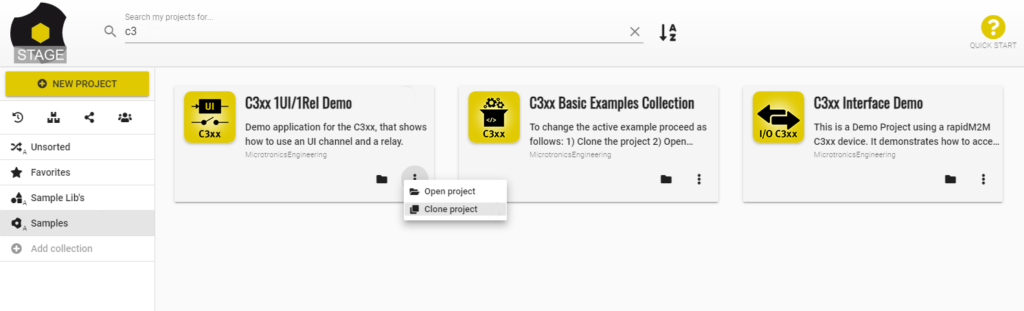
Trying it out and adapting it yourself
The complete source code of the demo IoT app is available via the rapidM2M Studio and contains extensive comments. Create a copy of the demo IoT app “C3xx 1UI / 1Rel Demo” and adapt the application to your requirements.