“C3xx Delayed Switch-Off Output Demo” is an IoT demo app for the myDatalogC3 that allows each relay to close separately for a specified time. After the configured delay time, it returns to the open state.

Platform Interface & Function
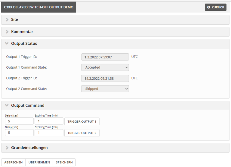
The application itself offers two main levels of configuration:
1. Output Status
This shows the last states of the commands that were sent to the unit. The “Trigger ID” is the time in which the command was sent including the configured “Expiring Time”.
The “Command State” reflects the state of the command. It shows whether the command was accepted or skipped by the unit.
2. Output Command
This enables commands to be sent to the unit. The “Delay” can be used to configure how long the relay should be closed.
In addition, it is possible to specify an “Expiring Time” to configure the validity of the command. This is useful if the unit is not in an online state and the command arrives late at the unit. Thus, the command is skipped in case of a timeout.
The button “Trigger Output” can be used to configure a triggering of the command. It is important here that the command is only sent to the unit by “accepting” or “saving” the current configuration.
Components of the demo IoT app
To cover the full range of IoT app functions, this demo includes a DLO, POV and BLO.
- DLO – Device Logic
In this demo, the device logic controls the switching of the relays and validates whether the time sent with the commands is still within the valid range.
- POV – Portal View
With a custom portal view, the standard interface was slightly adapted so that the commands can be activated with the help of buttons.
- BLO – Backend Logic
The backend logic extends the general API interface with a user-defined “extended API” interface. The BLO is integrated when the IoT app is installed and is executed on the server.
With the „extended API“,two further API interfaces are provided where users can send and retrieve their data.
The API endpoint “Command” is used to receive commands, check them, process them and then pass them on to the general API so that the change is sent on to the device. The API endpoint “Status” is used to read out the last states.
Insights into the BLO
For BLO usage, the playground will be used to send the corresponding API requests.
To send a valid request to the BLO, the following fields are relevant and must be adapted depending on the application and installation:
| Keyword | Description |
| DEV_PHASE |
Depending on the phase of the application, the endpoint is different.
|
| APM_ID |
The ID of the application model can be requested via the API.
|
| CUSTOMER | Name of the client from whom a site was created with the application. |
| SITE | Name of the site that was created. |
Endpoint – Command
With this endpoint it is possible to activate a relay for a certain time.
| Parameter | Limits |
| Delay (seconds) | 1 to 300 |
| Expiring Time (minutes) | 1 to 60 |
| Output | 1 to 2 |
					PUT /<DEV_PHASE>/<APM_ID>/taster/<CUSTOMER>/v1/<SITE>/command
{
  "delay": 5,
  "expiring_time": 1,
  "output": 2
}
Result
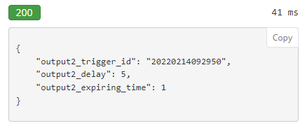
The “Result” returns those parameters that were calculated before the command was sent. The field “output2_trigger_id” is particularly interesting here. This is the ID that is also used by the unit for validating the command and is subsequently stored.
This also makes it possible to validate with external logic whether a certain command has arrived at the unit. This works by checking with the other endpoint whether the command has already been registered by the unit.
Endpoint – Status
The current status of the commands can be queried via the “Status” endpoint.
GET /<DEV_PHASE>/<APM_ID>/taster/<CUSTOMER>/v1/<SITE>/status
Result
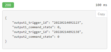
For each output, the calculated trigger ID and the corresponding command state are returned.
| Parameter | Description |
| trigger_id | Time of sending the command + Expiring Time |
| command_state | 0 –> Command Accepted 1 –> Command Skipped |
Try it out straight away!
The two “extended API” interfaces can also be tried out directly in the browser via the console (F12).
To do this, only the corresponding fields such as SERVER, CUSTOMER, SITE, APM_ID, USERNAME and PASSWORD need to be replaced.
Retrieving the status
					const server      = 'SERVER';
const customer    = encodeURIComponent('CUSTOMER');
const site        = encodeURIComponent('SITE');
const apmid       = encodeURIComponent('APM_ID')
const credentials = "USERNAME:PASSWORD";

const headers = new Headers();
headers.append('Authorization', 'Basic ' + btoa(credentials));
headers.append('Content-Type', 'text/json');

(async function() {
  const resp = await fetch(`${server}/api/extdev/${apmid}/demo/${customer}/v1/${site}/status`,
  { method:'GET', headers: headers});
  console.log(await resp.json());
})();
Sending a command
					const server      = 'SERVER';
const customer    = encodeURIComponent('CUSTOMER');
const site        = encodeURIComponent('SITE');
const apmid       = encodeURIComponent('APM_ID')
const credentials = "USERNAME:PASSWORD";

const headers = new Headers();
headers.append('Authorization', 'Basic ' + btoa(credentials));
headers.append('Content-Type', 'text/json');

const data = JSON.stringify({
 delay: 5,
 expiring_time: 1,
 output: 1
});

(async function() {
  const resp = await fetch(`${server}/api/extdev/${apmid}/demo/${customer}/v1/${site}/command`,
  { method:'PUT', headers: headers, body: data});
  console.log(await resp.json());
})();
This could also interest you

Modbus Master Library – simple, convenient implementation
Modbus is a communication protocol commonly used in industrial automation. The Modbus protocol consists of a client-server architecture in which a client (for example, a control device) sends commands to a server (for example, sensors or actuators) and receives data from it.
The communication is based on a simple command-response mechanism. Modbus is an open protocol, which among other things has led to its great popularity and spread.
The first steps with the myDatalogC3 – C3xx 1UI/1Rel Demo
Familiarize yourself with your myDatalogC3. The demo IoT app C3xx 1UI/1Rel shows in a few steps how the device works. At the end, you will get an outlook on how to create your own IoT app.
UI Trigger for myDatalogC330
The UI Trigger functionality provides the possibility to evaluate analog signals acquired via the UI channels with high sampling frequency (up to 1kHz) and to
