Energy saving is ubiquitous
In the meantime, we have become very accustomed to the progressive miniaturization of electronics. However, take a moment to admire what a common smartwatch can do these days. A high-resolution display, a powerful processor, multiple wireless interfaces and a suitable power source are integrated in a very small space.
The energy storage system, i.e. the battery, should keep pace with the development. With a smaller footprint, the capacity of the battery should ideally be even larger. Battery technologies are improving steadily, but the achievable energy density is developing more slowly [1] than the miniaturization of semiconductors is progressing (well known by the still valid “Moore’s Law” [2]).
The market for extremely energy-saving active components is therefore developing correspondingly quickly. Saving energy is now part of everyday life and good form in electronics development. Modern plug-in power supplies, such as a cell phone charger, no longer get red hot as they used to, although spectacular charging performance is now achieved with them.
Just as important as the right choice of components are energy-saving measures in the device firmware. You will feel this painfully in everyday life when a firmware update of poor quality halves the runtime of your smartphone.
Those who know the SoC have the runtime under control!
If you are developing a battery-powered product with a long field runtime and want to do without an oversized, i.e. unnecessarily bulky, battery for economic reasons or due to design aspects, then you will not be able to avoid consumption monitoring in addition to all energy-saving measures. This allows you to estimate the total and remaining runtime, as well as to use consumption-based operating states. For example, your smartphone reduces the screen brightness below a certain battery level or even throttles the computing power. Thus, the device knows the state-of-charge (SoC) of the built-in energy storage. To determine this, there are several approaches.
Determination of the SoC by measuring the open-circuit voltage
This amazingly simple method is sufficient for many applications where a reasonably constant load profile prevails, i.e. where the power consumption is not subject to strong fluctuations and is preferably only a fraction of the rated capacity.
Figure 1 shows the open circuit voltage (OCV) of some battery technologies as a function of the state-of-charge (SoC) [3], [4], [5], [6]. The top two battery types (lead-acid battery and alkaline cell) are well suited for the open-circuit voltage measurement method because a unique voltage value can be assigned to each SoC value. This method also works for lithium-ion batteries (bottom left), although the open-circuit voltage drops sharply at very low state of charge.
Lithium thionyl chloride batteries (bottom right), however, have the same open-circuit voltage throughout almost their entire service life. In these primary cells, which are very popular for long-life products, the open-circuit voltage is much more dependent on the ambient temperature than on the residual energy content. If you find such a battery in your drawer in an unknown state, you will not be able to find out whether the cell is full or almost empty without considerable measuring effort.

Inhomogeneous load profile – ambiguous open-circuit voltage measurements
Battery-powered IoT devices often have the characteristic of being in power-saving mode for long periods of time, only to wake up suddenly, usually due to an external stimulus. Subsequently, a data packet is to be sent via the built-in radio interface. The electronics require a comparatively large energy package for this short-term process. The very low current consumption in deep sleep mode is contrasted by a significantly higher current consumption in active mode. The load profile, i.e. the change over time of the load magnitude connected to the battery, is very uneven in this case.
Figure 2 shows measurement series from the Microtronics laboratory. A full and an empty alkaline battery are loaded with the same current pulse. Also in the picture: a simple, universal battery equivalent circuit describing the transient (short-time) behavior of the cell [7].
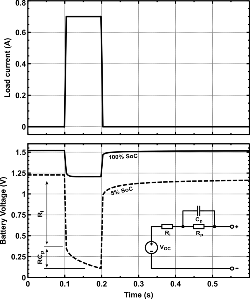
It can be clearly seen that in such a scenario, the open-circuit voltage measurement for determining the SoC reaches its limits. The internal resistance of the cell, which can be approximated from the voltage drop at a known load current, becomes larger the emptier the battery is:

Another disturbance is the transient behavior, which is more significant with empty batteries. The cell needs a “recovery time”, so to speak, to rise to the open-circuit voltage again. You can mitigate the resulting measurement errors with careful timing of the measurement point by never measuring the battery voltage after high-consumption operations (if these are known in the program sequence). It is also advantageous to maintain a suitable grace period between the load current peak and the measured value recording in order to suppress longer chemical recombination processes when the batteries are empty.
Convenient determination of the SoC by means of fuel gauges
Semiconductor manufacturers have recognized that determining the SoC is not trivial and offer you a wide range of so-called “fuel gauges”. These are usually optimized for a specific cell chemistry and can back-calculate the SoC from the battery voltage curve. Some of these ICs additionally measure the load current curve to achieve higher accuracy.
The Maxim MAX17048, which is used in the rapidM2M T32 in version 01v006, is able to determine the SoC sufficiently accurately through continuous battery voltage measurement alone. This is why this IC is one of the fuel gauges with particularly low intrinsic current consumption, since simultaneous current measurement is not required. The internal algorithm only works if the battery used reasonably matches the integrated model.
Although more advanced ICs support a wide range of capacitance due to their “learning” capability, fuel gauges are unsuitable for some application scenarios:
- When using primary cells with constant open-circuit voltage over a wide SoC range. These include, for example, the Li-SOCl2 battery in Figure 1 or zinc air button cells.
- When supplying a device via an agnostic input, where a fuzzily defined energy source is to be connected.
- When particularly accurate or high resolution measurements are required.
Coulomb Counter – Ideal for demanding applications
Coulomb is the unitfor electric charge. The electric current (in amperes) can also be called charge transport. If current of the magnitude of one ampere flows for one second, a charge of one coulomb is transported through the conductor during this time:

The unit for a coulomb is therefore the ampere-second. Another form of this, the milliampere hour (mAh), is known as the capacity specification of rechargeable batteries. A Coulomb Counter is therefore able to determine the actual charge consumed and consequently, if the total capacity is known, the residual charge in the battery.
Direct measurement of the charge transport is possible in principle[8], but almost all products on the market work by measuring the current via a shunt resistor. The shunt amplifier circuit in Figure 3 is already sufficient to form a universally usable Coulomb counter with a subsequent digital integrator stage. ICs such as the Dallas DS2740 [9] achieve considerable performance data with this simple principle, but can no longer be described as “ultra low power” due to the need for cyclic sampling.
Also worth mentioning is the difficulty of appropriately sizing the shunt resistor. Larger values allow for higher dynamic ranges, but produce a significant voltage dip when current is drawn in pulses, so undervoltage effects can occur.

Developed from the rapidM2M T32: A powerful Coulomb Counter
In an early development and concept phase of the rapidM2M T32, on the one hand only insufficient information about the actual dynamics of the energy absorption was known and on the other hand the battery type to be used was not yet specified exactly. As a consequence, it was decided that a Coulomb counter with significantly lower quiescent current consumption and greater dynamic range than the products available on the market was needed. The goal was to obtain a tool for optimizing energy consumption in the field. Unidirectional measurement is already sufficient for this purpose, i.e. only the charge transport from the energy source in the direction of the consumer must be measured.
The circuit implemented in the rapidM2M T32 (in version 01v005) is a completely new development, which can show significantly better values than the products available on the market at that time, both in terms of quiescent current consumption and dynamic range.

Figure 4 shows the operating principle. Via the shunt voltage controlled current source (with the transconductance gm), a charge proportional to the total charge transport accumulates in the capacitor C1, which is discharged above a defined threshold. Thus, one known charge transported from the energy source can be registered per pulse counted:

In order to derive a highly optimized end product from this initially obvious concept, the circuit was examined and optimized in the course of scientific work with regard to all limit operating states. The result is a finished module as a system-in-a-package, shown in Figure 5, with the author’s finger as a size comparison.
The performance data are impressive:
- Measuring range: 10µA – 1A
- Integrated shunt resistor: 200mΩ
- Quiescent current as sum of analog and digital part: < 3µA
- Communication interface: SPI
- Space requirement: < 113mm²